Categories
- Blog (58)
- News & Events (34)

For each Level 3 maintenance inspection, complete all Level 1 and Level 2 inspection items before making the following adjustments:
<1> Adjust the crosshead
1. Loosen the lock nut of the cross head adjusting screw, and withdraw the adjusting screw one turn.
2. Gently press your finger on the contact surface of the rocker arm to make the cross head contact with the valve stem end, and unscrew the cross head adjusting screw until it touches the valve stem end.
3. With the adjusting screw stationary here, tighten the locknut with 25-28 ft-lb (34-38 N.m). Use a wire gauge to check the clearance between the crosshead and valve spring seat, minimum 0.025 in. (0.64 mm).
<2> Adjust the injector (CUMMINS diesel engine with PT pump)
It is important to adjust the injector before adjusting the valve. When adjusting the injector, there is a slight load in the valve train, which will affect the valve clearance. Before adjusting the injector, use 30-35 ft-lb ( 41-47 N.m) torque to tighten the fixing screw of the fuel injection nozzle.
There are usually two methods for adjusting the fuel injector, (“torque method” and “dial gauge method”).
A. “Torque method”
1. Tighten the adjusting screw until the plunger touches the oil ring of the fuel injector, and then screw it in by 15 degrees to squeeze out the fuel in the cup.
2. Pull out the adjusting screw one turn.
3. Using an inch-pound torque wrench and a screwdriver, torque the adjusting screw to 60 inch-pound (68 N.m).
4. Hold the adjusting screw in place and tighten the nut to a torque of 40-45 ft-lb (54-61 N.m).
Note: When using the torque method for adjustment, the adjustment marks of the valve and fuel injection nozzle must be aligned with the correct position, otherwise the valve train of the diesel engine will be damaged.
b. “Dial Dial Method”
1. Install the dial indicator bracket and the dial indicator with extension rod (3375842) on the top of the injector plunger of the cylinder to be debugged.
2. Loosen the lock nut on the adjustment screw of the fuel injection nozzle, and tighten the adjustment screw until the plunger reaches the bottom of the oil cup of the fuel injection nozzle.
3. After screwing back 1/2 turn, screw the plunger to the bottom of the cup, and set the dial indicator pointer to zero.
4. Screw back the height adjustment screw until the reading on the dial indicator is the specified value.
5. Secure the adjusting screw and tighten the lock nut to a torque of 40-45 ft-lb (54-61 N.m).
6. Use the special tool to pull the fuel injection plunger several times to check the reading of the dial indicator. The reading of the dial indicator must be within the tolerance range.
Note: The dial gauge extension rod is firmly fixed on the dial gauge mandrel, but it cannot be in contact with the rocker arm. The lead of the fuel injector must be accurate, otherwise the wrong adjustment will cause the oil cup to break. Be careful to align the column Whether the plug reaches the bottom of the cup, the adjustment screw should not be over-tightened before the pointer of the dial indicator reaches zero.
<3> Adjust the valve clearance
At the valve mark, find the adjustment cylinder position.
1. Loosen the lock nut on the valve adjusting screw, and unscrew the adjusting screw until the rocker arm is loose.
2. Insert a thickness gauge between the rocker arm and the top of the crosshead. See the table below for the appropriate clearance of intake and exhaust valves:
Valve adjustment (data applicable)
Oil Temperature Valve Clearance Inches (mm)
intake valve exhaust valve
Cool (70°F/21°C) 0.014(0.36) 0.027(0.69)
Thermal (140°F/60°C) 0.012 (0.30) 0.024 (0.61)
3. Unscrew the adjusting screw until the rocker arm just touches the feeler gauge (thickness gauge). Keeping the adjusting screw in the adjusted position, tighten the locknut with a torque of 40-45 ft-lb (54-61 N.m).
Note: Adjust the hours and minutes for “Cold” and “Hot”. “Cold Tuning”: The diesel engine should not work (at least four hours) at the ambient temperature to be adjusted to reach a stable temperature; “Hot Tuning”: When the engine oil temperature is above (140°F/60°C), press the heat speed value Adjust the fuel injector and valve. If there is no thermometer, run the engine at rated speed and load or at high idle speed for at least 20 minutes, then stop immediately for adjustment.
<4> Cleaning the water tank
Clean the dust and oil on the surface of the water tank. If there is a problem with the water temperature, clean it with a cleaning solution: the cleaning solution is composed of 150 grams of Hener and six liters of water. Before cleaning, drain all the water in the cooling system, then pour in the same amount of cleaning solution, stay for 8-12 hours, then run the diesel engine, stop when the water temperature reaches the working temperature of 160°F (74°C), and release the cleaning solution immediately.
<5> Generator part
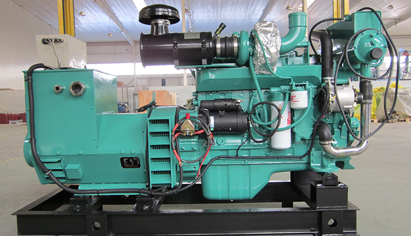
Check the generator bearings, add new high-temperature lubricating grease if necessary, and check whether the control circuit is aged or damaged.
Note: In order to make the diesel engine run normally, the fuel injection nozzle and valve must always be adjusted correctly. One of these two items controls the intake and exhaust of the diesel engine, and the other controls the fuel intake and exhaust. The fuel injection nozzle and valve clearance are accurate Whether or not it has a great relationship with the power and fuel consumption of the generator set.
Warning: The adjustment of fuel injector and valve clearance must be operated or guided by professional technicians, otherwise it is easy to cause generator set failure or destructive damage to the set!
